

Volvo 850 turbo basic testing service manual
F – BASIC TESTING – TURBO
1995 Volvo 850
1995 ENGINE PERFORMANCE
Volvo – Basic Diagnostic Procedures
850 – Turbo
INTRODUCTION
NOTE: In this article, Engine Control Module (ECM) may also be referred to as Engine Control Unit (ECU).
The following diagnostic steps will help prevent overlooking
a simple problem. This is also where to begin diagnosis for a no-start condition.
The first step in diagnosing any driveability problem is verifying the customer complaint with a test drive under the conditions the problem reportedly occurred.
Before entering self-diagnostics, perform a careful and complete visual inspection. Most engine control problems result from mechanical breakdowns, poor electrical connections or damaged/ misrouted vacuum hoses. Before condemning the computerized system, perform each test listed in this article.
NOTE: Perform all voltage tests using a Digital Volt-Ohmmeter (DVOM) with a minimum 10-megohm input impedance, unless otherwise instructed in test procedure.
PRELIMINARY INSPECTION & ADJUSTMENTS
VISUAL INSPECTION
Visually inspect all electrical wiring. Look for chafed, stretched, cut or pinched wiring. Ensure electrical connectors fit tightly and are not corroded. Ensure vacuum hoses are properly routed and not pinched or cut. See M – VACUUM DIAGRAMS – TURBO article to verify routing and connections (if necessary). Inspect air induction system for possible vacuum leaks.
MECHANICAL INSPECTION
Compression
Check engine mechanical condition using a compression gauge, vacuum gauge or engine analyzer. See engine analyzer manual for specific instructions.
WARNING: Do not use ignition switch during compression tests on fuel injected vehicles. Use a remote starter to crank engine. Fuel injectors on many models are triggered by ignition switch during cranking mode, which can create a fire hazard or contaminate engine oiling system.
COMPRESSION SPECIFICATIONS TABLE
Application Specification (Minimum) Compression Pressure ……….. 156-185 psi (11-13 kg/cm )
Exhaust System Backpressure
1) Exhaust system can be checked using a vacuum or pressure gauge. Remove oxygen sensor or air injection check valve (if equipped).
2) Connect a 1-10 psi pressure gauge, and run engine at 2500
RPM. If exhaust system backpressure is greater than 1 3/4-2 psi, exhaust system or catalytic converter is plugged.
3) If using a vacuum gauge, connect vacuum gauge hose to intake manifold vacuum port and start engine. Observe vacuum gauge. Open throttle part way and hold steadily. If vacuum gauge reading slowly drops after stabilizing, exhaust system should be checked for a restriction.
FUEL SYSTEM
WARNING: Always relieve fuel pressure before disconnecting any fuel injection-related component. DO NOT allow fuel to contact engine or electrical components.
FUEL PRESSURE
Fuel Pressure
1) Before disconnecting, cover fuel line connector using shop towel to absorb any fuel spray. Connect Fuel Pressure Gauge (5011) between fuel line and fuel rail. Seal free end of hose using Plug (5266) or use Fuel Drainage Unit (981 2270, 2273 and 2282).
2) Lift cover on central electrical unit located in engine compartment and remove fuel pump relay. See Fig. 1.
3) Connect a jumper wire between relay terminals No. 1 and 3. See Fig. 2.
4) Turn ignition on. Fuel pump should start. Fuel filler
cover can be removed to determine whether main pump is operating. Fuel pressure should be about 43.5 psi (3.06 kg/cm ). If pressure is too low, pinch return hose by hand and check whether pressure rises. DO
NOT allow pressure to exceed 86 psi (6 kg/cm ).
5) If pressure rises rapidly, pump and lines are okay. Replace pressure regulator and recheck line pressure. If pressure rises slowly, fuel filter, fuel pump strainer or fuel lines are blocked. If pressure does not rise, fuel pump is probably faulty.
6) If pressure is too high, remove jumper wire between relay or fuse terminals. Remove return hose from pressure regulator. Blow in pipe. Remove vacuum hose from pressure regulator. Blow in pipe. If

both hoses are open, pressure regulator is defective. Replace regulator and recheck pressure.
Fig. 1: Locating Fuel Pump Relay
Courtesy of Volvo Cars of North America.

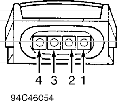
Fig. 2: Identifying Fuel Pump Relay Terminals
Courtesy of Volvo Cars of North America.
NOTE: ECU terminal identifications are marked on unit or connector. CAUTION: Ensure ignition is off when connecting or disconnecting ECU
connector.
Fuel Pump Circuit
1) If fuel pump does not operate with ignition on, remove fuel pump relay. See Fig. 1. Connect jumper wire between fuel pump relay terminals No. 1 and 3. See Fig. 2. Turn ignition on. If fuel pump does not start, go to next step. If fuel pump starts, replace fuel pump relay.
2) Turn ignition off. To check relay ground, connect ohmmeter between ground and fuel pump relay terminal No. 2. See Fig. 2.
Ohmmeter should indicate about zero ohms. If ohmmeter does not indicate about zero ohms, check wiring between fuel pump relay and ground.
3) To check fuel pump relay voltage supply, connect voltmeter between ground and fuel pump relay terminal No. 1. See Fig. 2 . Turn
ignition on. Battery voltage should be present. If battery voltage is not present, check wiring between fuel pump relay and fuse No. 2.
4) Turn ignition off. Connect ohmmeter between ground and relay terminal No. 3. See Fig. 2. About 1.5 ohms should be present. If about 1.5 ohms are not present, check resistance at fuel pump
connector to determine whether fault is in pump or wiring.
5) To check fuel injection control signal to fuel pump relay, connect voltmeter between ground and fuel pump relay terminal No. 4. See Fig. 2. Operate starter motor. If voltmeter indicates about 3 volts, replace relay.

6) If voltage is not to specification, check wiring between fuel pump relay and ECU. If wiring is okay, see ELECTRONIC CONTROL UNIT – IGNITION in the I – SYSTEM/COMPONENT TESTS – TURBO article.
Fig. 3: Connecting Breakout Box To ECU (Typical) Courtesy of Volvo Cars of North America.
IGNITION CHECKS
MOTRONIC 4.3
No Start
1) Determine if fault is fuel or ignition. Check fuel pressure. See FUEL PRESSURE under FUEL SYSTEM. If fuel pressure is not as specified, repair fuel system as necessary. If fuel pressure is as specified, fuel system is okay, check for spark. Go to next step.
2) Using a high output spark tester, check for spark at end of one spark plug wire. If spark is not present, go to next step. If spark is present, remove and inspect all spark plugs. Replace spark plugs as necessary. Try to start engine. If engine starts, fault was due to spark plugs. If engine does not start, check for defective mass airflow sensor or engine coolant temperature sensor. See procedures in the K – SENSOR RANGE CHARTS – TURBO article.
3) Disconnect RPM sensor connector. Using an ohmmeter, measure resistance between sensor connector terminals. If resistance
is 200-500 ohms, RPM sensor is okay. Go to next step. If resistance is not 200-500 ohms, replace RPM sensor.
4) Turn ignition off. Install Breakout Box (981-3190) to ECU. See Fig. 3. Turn ignition on. Set DVOM scale to measure frequency. Connect a DVOM between terminals A21 and A42. Observe DVOM and operate starter motor. If frequency is 1.5-2.0 Hz, go to next step. If frequency is not 1.5-2.0 Hz, a fault exists in Camshaft Position (CMP) sensor circuit. Repair circuit or replace defective CMP sensor and retest.
5) Turn ignition off. Disconnect ignition coil 4-pin connector. Measure voltage between ground and terminal No. 3 of ignition coil connector. See Fig. 4. If battery voltage is present, go to next step. If battery voltage is not present, check No. 4 fuse. Replace fuse as necessary. If fuse is okay, locate and repair open in wire between terminal No. 3 of ignition coil connector and fuse No. 4.
Fig. 4: Identifying Ignition Coil Connector Terminals
Courtesy of Volvo Cars of North America.
6) Turn ignition off. Wait about 3 minutes. Measure resistance between ground and terminal No. 1 of ignition coil
connector. See Fig. 4. If resistance is zero ohms, go to step 8). If resistance is not zero ohms, go to next step.
7) Turn ignition off. Disconnect and inspect ignition coil 4- pin connector. Clean or repair connector as necessary. Measure resistance between ground and terminal No. 1 of coil connector. See Fig. 4. If resistance is zero ohms, cleaning ignition coil connector corrected fault. If resistance is not zero ohms, locate and repair
open in terminal No. 1 wire.
8) Turn ignition on. Set DVOM to measure frequency. Measure frequency between ground and terminal No. 4 of ignition coil connector while operating starter motor. See Fig. 4. If frequency is 8 -10 Hz, circuit is okay. Go to step 11). If frequency is not 8-10 Hz, go to next step.
9) Turn ignition on. Measure voltage between ground and terminal No. 4 of ignition coil connector. If voltage is 0-1 volt, go to next step. If voltage is not 0-1 volt, check wire between terminal No. 4 of coil connector and terminal B11 of ECM connector for short to voltage. Repair as necessary.
10) Turn ignition off. Wait about 3 minutes. Disconnect ECM connector. Measure resistance between ground and terminal No. 4 of ignition coil connector. See Fig. 4. If resistance is infinite, check for intermittent open in wire between terminal No. 4 of coil connector and terminal B11 of ECM connector. If resistance is not infinite,
check for short to ground in wire between terminal No. 4 of coil connector and terminal B11 of ECM connector.
11) Turn ignition off. Connect ignition coil connector. Turn ignition on. Disconnect coil wire from distributor cap. Hold end of coil wire about 3-5 mm from ground. Operate starter and check for spark. If spark is present, go to next step. If spark is not present, replace ignition coil and retest.
12) Reconnect ignition coil wire. Try to start engine. If engine starts, fault was due to poor connection at ignition coil. If engine does not start, check distributor cap and rotor for cracks, moisture or dirt. Repair as necessary.
IDLE SPEED & IGNITION TIMING
NOTE: Idle speed and ignition timing are not adjustable. See the IDLE SPEED & CO LEVEL and IGNITION TIMING tables for specifications.
IDLE SPEED & CO LEVEL TABLE (1)
Application Idle RPM (2) CO Level Turbo ……………………. 850 ……….. .20-1.0% (1) – Idle speed/CO level can only be checked, not adjusted.
(2) – Measured upstream of catalytic converter with oxygen
sensor connected.
IGNITION TIMING TABLE (Degrees BTDC @ RPM)
Application (1) Timing Turbo ……………………………….. 4-8 @ 750-850 (1) – Ignition timing computer-controlled. Not adjustable.
SUMMARY
If no faults found while performing DIAGNOSTIC PROCEDURES, proceed to G – TESTS W/CODES – TURBO article. If no hard codes are found in self-diagnostics, see the H – TESTS W/O CODES – TURBO article for diagnosis by symptom (i.e., ROUGH IDLE, NO START, etc.) or intermittent diagnostic procedures.