
1994 Volvo 960
1994 ENGINE PERFORMANCE
Volvo Self-Diagnostics
960
If no faults were found while performing BASIC DIAGNOSTIC PROCEDURES, proceed with SELF-DIAGNOSTIC SYSTEM. If no fault codes or only pass codes are present, proceed to H - TESTS W/O CODES article in the ENGINE PERFORMANCE Section for diagnosis by symptom (i.e., ROUGH IDLE, NO START, etc.).
NOTE: All voltage tests should be performed using a Digital Volt-Ohmmeter (DVOM) with a minimum 10-megohm input
impedance, unless specifically stated otherwise in testing procedures.
960 uses a Motronic 1.8 diagnostic system, which uses a single Electronic Control Unit (ECU) to control fuel injection and ignition systems. In addition, Motronic 1.8 diagnostic system determines whether A/C compressor may be switched on, reduces engine torque in response to a signal from automatic transmission, and controls radiator fan.
Diagnostic unit for retrieving codes is located in engine compartment, in front of left strut assembly. Diagnostic unit is equipped with an LED indicator, activation button and function select cable. See Fig. 1.
Diagnostic unit output socket No. 2 is used to retrieve all codes. Once selector cable has been inserted in correct slot, depressing button once, twice or 3 times selects from one of 3 control (fault tracing) functions. Faults stored in ECU memory are read by observing LED flashes. Diagnostic system stores 18 fault codes.
All fault codes contain 3 digits (example: 4-1-3). Since codes have 3 digits, each code requires 3 series of flashes. A 3- second interval separates series of flashes. See Fig. 2.
Fig. 1: Identifying Diagnostic Unit Courtesy of Volvo Cars of North America.

Fig. 2: Counting Red LED Code Flashes For Code 2-1-3 Courtesy of Volvo Cars of North America.
RETRIEVING CODES
CAUTION: Never disconnect or connect ECU connector with ignition switch in ON position. Ensure ignition is off and fuse No.
24 is removed.
ECU is equipped with diagnostic functions in form of self- diagnostics (Test Mode No. 1), function testing (Test Mode No. 2) and control testing (Test Mode No. 3). Access to diagnostic system is provided by socket No. 2 on diagnostic unit with ignition on.
Test Mode No. 1 (Retrieving Codes)
ECU can record 18 fault codes. Fault codes stored in memory can be displayed by pressing test button "A" on diagnostic unit for an instant. Control unit memory can retain codes from 10 minutes to 24 hours after interruption of electrical supply.
Control unit will begin to use a faulty or missing signal immediately after it has been corrected rather than remaining in limp- home mode. Fault code, however, will remain in memory.
To retrieve codes, open diagnostic unit cover and connect test lead to socket No. 2. Turn ignition on. Enter test mode No. 1 by pressing test button once for 1-3 seconds.
Observe LED, and count number of flashes in 3 digit series comprising a fault code. Because series are displayed at 3-second intervals, codes can be easily distinguished.
If a fault code is retrieved, refer to FAULT CODES table under FAULT CODE DEFINITION. Depress push button again, and check for additional codes. Depress push button a third time if necessary. If first code repeats, no other codes are present. Control unit can store all 18 codes simultaneously.
Test Mode No. 2
This function is activated by briefly pressing test button "A" 2 times, causing LED to rapidly flash. Control unit will flash a code indicating receipt of a signal from following components:
3-3-2 - Throttle switch (throttle moved from idle).
3-3-3 - Throttle switch (throttle moved from WOT).
1-2-4 - Starter inhibitor switch, when gear selector is moved from a drive position to N or P.
1-4-1 - Timing pick-up, when starter motor is running.
1-1-4 - ECC control panel, when A/C button is depressed or released.
1-3-4 - Relay in ECC power unit energizing A/C compressor clutch when A/C is on.
Test Mode No. 3
This function is activated by briefly pressing test button "A" 3 times. Control unit will respond by activating following components in order:
Radiator fan at half speed for 3 seconds.
Radiator fan at full speed for 3 seconds.
Fuel injectors.
Idling (CIS) valve.
Relay in ECC power unit, resulting in A/C clutch operation.
FAULT CODE DEFINITION
FAULT CODES TABLE
Code Fault Repair 1-1-1 ........... No Faults ..................... None
1-1-2 .............. ECU ................. Replace ECU
1-1-3 ......... Fuel Injectors ........ ( 1) Check Fuel
Injectors, Heated Oxygen Sensor
& Airflow Meter 1-2-1 .......... Mass Airflow ..... ( 1) Check Airflow
Signal Meter & Main Relay 1-2-3 ...... Coolant Temperature ... ( 1) Check Sensor
Sensor Signal
1-3-1 ..... Timing Pick-Up Signal ................ ( 2)
1-3-2 ........ Battery Voltage ................... ( 2)
1-4-3 ... No Front Knock Sensor Signal ........... ( 2) 2-1-2 ...... Oxygen Sensor Signal ... ( 1) Check Oxygen
Sensor 2-1-4 ..... Timing Pick-Up Signal ................ ( 2)
2-2-3 ..... No Idle Valve Signal ................. ( 2)
2-3-1 ....... Lambda Rich/Lean ................... ( 2)
In Part-Load Range
... Lambda Rich/Lean At Idle ............... ( 2)
.. Idle Control Not In Range ............... ( 2) 2-4-1 ....... EGR Flow Too Low ................... ( 2)
2-4-3 .... Throttle Switch Signal ................ ( 2) Absent Or Faulty
3-1-1 ...... Speedometer Signal .................. ( 2)
3-1-4 .... Camshaft Sensor Signal ................ ( 2)
3-2-2 .... Airflow Meter Hot Wire ................ ( 2)
4-3-1 .... EGR Temperature Sensor ................ ( 2)
Absent/Faulty
4-3-3 ..... No Rear Knock Sensor ................. ( 2)
Signal
- See I - SYSTEM/COMPONENT TESTS article in the ENGINE PERFORMANCE Section.
- See FAULT CODE TESTING under SELF-DIAGNOSTIC SYSTEM.
FAULT CODE TESTING
Code 1-3-1 Or 2-1-4 (Timing Pick-Up Signal)
Enter test mode No. 2. See TEST MODE NO. 2 under RETRIEVING CODES. Operate starter motor. Code 1-4-1, indicating a timing pick-up signal, should be displayed.
Disconnect ECU connector. Connect a voltmeter capable of measuring millivolts between ECU connector terminals No. 47 (Pink wire) and No. 48 (White/Black wire). Operate starter motor. Voltmeter should indicate 300-400 millivolts.
Turn ignition off. Connect an ohmmeter between timing
pick-up connector terminals No. 47 (Pink wire) and No. 48 (White/Black wire). Resistance should be approximately 200-400 ohms.
Reconnect ECU with Measuring Unit (999-3070) connected to ECU. See Fig. 3. Connect an ohmmeter between measuring unit terminals No. 48 and 19. Resistance should be zero ohms. Measure resistance between terminals No. 48 and 30. Resistance should be zero ohms. On automatic transmission equipped vehicles, check test mode No. 1 if speed signal fault code is displayed. See TEST MODE NO. 1 under RETRIEVING CODES.
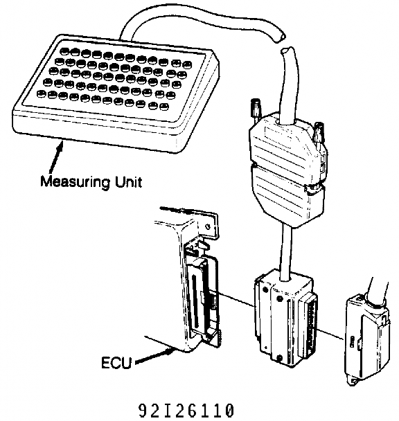
Fig. 3: Connecting Measuring Unit (999-3070) To ECU Courtesy of Volvo Cars of North America.
Code 1-3-2 (Battery Voltage)
This code is set if battery voltage decreases to less than
8 volts or exceeds 16 volts for 5 seconds after engine start. To check, connect Measuring Unit (999-3070) to ECU. See Fig. 3. Connect voltmeter between measuring unit terminals No. 18 and 19.
Start engine and check battery voltage. Check battery and charging system if voltage is too low or high.
Code 1-4-3 Or 4-3-3 (No Front/Rear Knock Sensor Signal) Disconnect knock sensor connector and jumper terminals.
Measure resistance between knock sensor terminal No. 2 (Green/Gray wire) and terminal No. 11 (Green wire) or terminal No. 29 (Brown/Orange wire), depending upon whether front or rear knock sensor is being checked. If zero ohms is present, replace knock sensor. Tighten sensor to 15 ft. lbs. (20 N.m).
Code 2-2-3 (No Idle Valve Signal)
Check operation of idle valve in test mode No. 3. See TEST MODE NO. 3 under RETRIEVING CODES. If valve does not operate, check wiring.
Connect Measuring Unit (999-3070) to ECU. See Fig. 3. Start engine. Connect voltmeter between measuring unit terminals No. 4 and 24. Approximately 11 volts should be present. Connect voltmeter between measuring unit terminals No. 22 and 24. Approximately 7.5 volts should be present.
Turn engine off (ignition on). Using a voltmeter, check voltage at measuring unit terminals No. 4 and 22. Voltage should be approximately 8-9 volts. If no voltage is present, check wiring to idle valve.
Turn ignition off. Using an ohmmeter, check resistance across measuring unit terminals No. 4 and 22. Resistance should be approximately 25 ohms. If not, replace idle valve.
Code 2-3-1 (Lambda Control Rich Or Lean In Part-Load Range) Or Code 2-3-2 (Lambda Control Rich Or Lean At Idle)
Control unit receives information from oxygen sensor on whether fuel/air mixture is too rich or too lean in part-load and idling ranges. Control unit adaptive system compensates for this by making mixture leaner or richer as necessary. If mixture must be compensated excessively, a fault code is set.
Start engine. Connect voltmeter between terminals No. 1 and 2 in starter motor 2-pin connector. Voltmeter should indicate battery voltage. If no voltage is present, check fuse No. 30.
Stop engine. Disconnect starter motor connector. Connect ohmmeter between starter motor connector terminals No. 1 and 2. Ohmmeter should show 3-13 ohms, depending on resistor temperature.
Connect Measuring Unit (999-3070) to ECU. See Fig. 3. Start engine. Connect voltmeter between measuring unit terminals No.
28 and 30. After a short interval, voltmeter should oscillate between 0.1-1.0 volt.
If voltage remains constant at zero volts, sensor is interpreting fuel/air mixture as lean. If voltage is constant at one volt, sensor is interpreting fuel/air mixture as rich.
If either fault code 2-3-1 or 2-3-2 is displayed and voltmeter is oscillating between 0.1-1.0 volt, Lambda control is correctly adjusting CO content even though ECU is indicating fault.
Code 2-3-3 (Idle Control Not In Range)
If control unit has to open or close idling valve too much to maintain constant idling conditions, control unit will interpret this as a fault and record a fault code.
Start engine, and run it until it reaches normal operating temperature. Ensure gear selector is in Neutral and A/C is off. To determine whether an air leak is present, clamp air valve hose and observe engine speed. If engine speed exceeds 600-700 RPM, air leakage
is present or throttle disc is incorrectly adjusted.
Code 2-4-1 (EGR Flow Too Low)
Enter test mode No. 3. See TEST MODE NO. 3 under RETRIEVING CODES. Turn ignition on. Press test button on diagnostic unit 3 times for more than one second each. Light should flash as EGR converter is activated. Turn ignition off.
If EGR converter is not activated, measure resistance between pins No. 6 (Blue wire) and No. 15 (Red/Green wire). Resistance should be about 75-95 ohms. If resistance is not as specified, check wiring and connectors.
Disconnect EGR converter connector, located next to power steering fluid reservoir. See Fig. 4. Remove wire directly opposite Black/White wire between pin No. 1 and control unit. Reconnect connector.
Start engine, and run it until it reaches normal operating temperature. Touch loose lead to engine ground. If engine starts to run unevenly, EGR system is operating correctly.

Fig. 4: Locating EGR Converter Connector Courtesy of Volvo Cars of North America.
Code 2-4-3 (Throttle Switch Signal Absent Or Faulty)
Enter test mode No. 2. See TEST MODE NO. 2 under
RETRIEVING CODES. Turn throttle slightly. Throttle function is correct in idling position if flashing code 3-3-2 is displayed.
Turn throttle to full-load position and release. Throttle function is correct in full-load position if flashing code 3-3-3 is displayed.
Connect Measuring Unit (999-3070) to ECU. See Fig. 3. Turn ignition on. Connect voltmeter between measuring unit terminals No. 30 and 53. Voltmeter should indicate about 0.5 volts at idle and about 4.
5 volts at full load.
Connect voltmeter between measuring unit terminals No. 12 and 30. Voltmeter should indicate 5 volts. Turn ignition off. Ensure measuring unit terminal No. 30 is grounded. Connect an ohmmeter between measuring unit terminals No. 19 and 30. Ohmmeter should indicate zero ohms.
Code 3-1-1 (Speedometer Signal)
Control unit is dependent on this signal for WOT enrichment, fan control, etc. A fault code will be set if speed exceeds 3390 RPM, load signal corresponds to part load and signal is absent for 3 seconds.
To check speedometer signal, raise vehicle with rear wheels suspended. Connect Measuring Unit (999-3070) to ECU. See
Fig. 3. Connect voltmeter between measuring unit terminals No. 9 and
19. Turn ignition on. Spin rear wheels, and check voltmeter. Voltage should be 0.1-12.0 volts.
If voltage is not present, check wiring between control unit and instrument cluster. Connect ohmmeter between measuring unit terminal No. 9 and terminal at rear of instrument cluster (Green/Orange wire). Ohmmeter should indicate zero ohms.
If no reading is obtained, check wiring between instrument cluster and control unit. If reading is obtained, check wiring between instrument cluster and rear axle. On A/T models, check test mode No. 1 if speed signal fault is obtained. See TEST MODE NO. 1 under RETRIEVING CODES.
Code 3-1-4 (Camshaft Sensor Signal)
Camshaft sensor enables control unit to determine which cylinder requires fuel and ignition. A fault code is recorded if signal remains constantly high or low for more than 30 seconds.
To check camshaft sensor signal, remove fuse No. 31 to prevent engine from starting and connect Measuring Unit (999-3070) to ECU. See Fig. 3. Turn ignition switch to ON position. Connect voltmeter across measuring unit terminals No. 8 and 19. Operate starter motor. Voltage should oscillate between .1 and .5 volt. Install fuse No. 31.
If signal is absent or faulty, ensure voltage across measuring unit terminals No. 10 and 30 is about 11 volts. Turn ignition off. Ensure measuring unit terminal No. 30 is grounded. Connect an ohmmeter between measuring unit terminals No. 30 and 19. Ohmmeter should indicate zero ohms.
Code 3-2-2 (Airflow Meter Hot Wire)
Approximately 4 volts is routed to platinum wire in airflow meter from ECU terminal No. 5. Ground is supplied from ECU terminal No. 7. Fault code is set if voltage between ground and terminal No. 7 does not exceed 2.5 volts.
Turn ignition off. Connect Measuring Unit (999-3070) to ECU. See Fig. 3. To ensure airflow meter is grounded, connect ohmmeter between measuring unit terminals No. 19 and 26. Zero ohms should be present. Connect ohmmeter between airflow meter connector terminal No.
(Brown wire) and ground. Reading should be about zero ohms.
Connect ohmmeter between measuring unit terminals No. 7 and 26. Reading should be about 2.5-4.0 ohms. If resistance is not to
specification, measure resistance between airflow meter terminals No.
(Brown/White wire) and No. 3 (Green/Yellow wire).
Turn ignition on. Connect voltmeter between measuring unit terminals No. 7 and 19. About 1.4 volts should be present. Start engine. Voltage should increase to 2.3-2.6 volts when idling. Voltage should be 2.3 volts with engine hot.
If voltage reading is too low, connect voltmeter between measuring unit terminals No. 25 and 19. Increase speed to 1800 RPM, and stop engine. Voltage should be about 4 volts. On A/T models, check test mode No. 1 if load signal fault code is displayed. See TEST MODE NO. 1 under RETRIEVING CODES.
Code 4-3-1 (EGR Temperature Sensor Absent/Faulty)
Measure resistance between terminals No. 14 (Black wire) and No. 22 (Yellow/Black wire). Resistance should be 500-1000 ohms. If resistance is not 500-1000 ohms, check wiring, connectors and ground terminal on intake manifold.
CLEARING CODES
Turn ignition on. Display fault codes. Operate test button for more than 5 seconds. Release test button. LED should light after 3 seconds. Press button again for more than 5 seconds. Release button. LED should be out.
Ensure fault codes have been cleared by pressing test button once for more than one second (but not more than 3 seconds). Fault codes have been cleared if code 1-1-1 is displayed.
ECU LOCATION
ECU is located above accelerator pedal.
If no hard fault codes (or only pass codes) are present, driveability symptoms exist or intermittent codes exist, proceed to H - TESTS W/O CODES article in the ENGINE PERFORMANCE Section for diagnosis by symptom (i.e., ROUGH IDLE, NO START, etc.) or intermittent diagnostic procedures.
Disclaimer: Volvotips has the exclusive courtesy of Volvo Car Corporation and Volvo Cars Heritage to publish the Volvo Greenbooks (service manual), parts catalogs and other Volvo-material and publications. Commercial use and publishing at other websites of these items is prohibited.