
1994 Volvo 960
1994 STEERING
Volvo - Steering Columns
960
Steering column upper and lower sections are connected by a flange. On frontal impact, flange breaks from upper column. Upper column is supported by bearings in jacket tube or bearing housing.
WARNING: Before performing any repairs, disconnect and shield negative battery cable from ground. Disconnect Yellow and Orange Supplemental Restraint System (SRS) connectors on driver’s side of center console, near accelerator pedal, to avoid accidental air bag deployment. Follow air bag service precautions. See SERVICE PRECAUTIONS in the
AIR BAG RESTRAINT SYSTEM article in the ACCESSORIES/
SAFETY EQUIPMENT section. Disable SRS before removal.
WARNING: NEVER disconnect crash sensor connector or standby power unit to disable SRS system.
Disconnect and shield negative battery cable. Locate and disconnect Orange and Yellow SRS connectors on driver’s side of center console, under carpet. See Fig. 1. DO NOT disconnect harness connection at crash sensor or air bag will deploy.
After repairs, ensure all wiring and component connectors are reconnected. To activate air bag system, reconnect Orange and Yellow SRS connectors on driver’s side of center console, under carpet. Reconnect negative battery cable. Turn ignition switch to ON position (engine not running). If no fault codes are present, SRS warning light should go out after 10 seconds.
Fig. 1: Locating SRS Disabling Connectors (Typical) Courtesy of Volvo Cars of North America
CONTACT REEL CENTERING
If contact reel is new, remove new contact reel shipping pin from pin hole. See Fig. 2. Turn contact reel pin to far right and then left about 3 turns until pin hole is at proper position. See CONTACT REEL PIN HOLE POSITION table. Lock contact reel in proper position with shipping lock screw.
CONTACT REEL PIN HOLE POSITION TABLE
Model Pin Hole Position
960 ............................................ 8 O’clock

Fig. 2: Centering Contact Reel (Typical) Courtesy of Volvo Cars of North America
Carefully pull contact reel wiring with plastic warning label through hole in steering wheel. Install steering wheel so
contact reel pin aligns with proper pin alignment hole in steering wheel.
Install steering wheel hub retaining bolt finger tight to ensure steering wheel does not come off shaft when removing contact reel shipping lock screw.
Remove shipping lock screw from contact reel pin. Install original lock screw, with plastic warning label attached, into original retaining screw hole in steering wheel. Tighten steering wheel hub retaining bolt to specification. See TORQUE SPECIFICATIONS.
Connect SRS Special Test Resistor (998-8695) to contact reel wiring connector in place of air bag module. See Fig. 3. Activate SRS. See DISABLING & ACTIVATING AIR BAG SYSTEM .

Fig. 3: Installing SRS Special Test Resistor (998-8695) On Module Connector
Courtesy of Volvo Cars of North America
Turn ignition switch to ON position and ensure SRS warning light goes out after 10 seconds. If light does not go out, a fault code is set and memory must be cleared. After clearing fault codes, recheck SRS light operation. Perform SYSTEM OPERATION CHECK. See
AIR BAG RESTRAINT SYSTEM article in the ACCESSORIES/SAFETY EQUIPMENT
section.
If SRS warning light goes out after about 10 seconds, turn off ignition, disconnect negative battery cable and remove Special Test Resistor (998-8695) from air bag module connector. Position air bag module to steering wheel, and install wiring connector. Ensure wiring connector clicks into position. Install air bag module and steering wheel. See STEERING WHEEL & AIR BAG MODULE under REMOVAL & INSTALLATION.
STEERING WHEEL & AIR BAG MODULE
CAUTION: Disconnect negative battery cable prior to working on steering column. DO NOT reconnect battery and turn ignition on when removing air bag assembly. If air bag assembly has been removed and voltage is applied to SRS circuit, a fault code will be displayed and SRS light will be activated. DO NOT disconnect harness connection at crash sensor or air bag will deploy.
Removal
Ensure front wheels are pointing straight-ahead. Mark steering wheel to column location for installation reference. Turn ignition key to position No. 1 to disengage steering column lock. Remove steering column lower cover panel and knee bolster assembly. See Fig. 4. Disable air bag system. See
DISABLING & ACTIVATING AIR BAG SYSTEM . Remove 2 Torx No. 30 screws
from rear of steering wheel. See Fig. 5.

Fig. 4: Removing Knee Bolster
Courtesy of Volvo Cars of North America

Fig. 5: Identifying SRS Air Bag Module Courtesy of Volvo Cars of North America
Pull air bag module away from steering wheel and disconnect wiring connector. Remove air bag module.
Remove steering wheel hub retaining bolt. Remove plastic warning label retaining screw from steering wheel, leaving screw attached to plastic warning label. Carefully pull steering wheel from column, allowing wiring and plastic warning label to pass through hole in steering wheel. See Fig. 6.

Fig. 6: View Of Wiring & Plastic Label On Steering Column (Typical) Courtesy of Volvo Cars of North America
Installation
Align steering wheel so pin on contact reel is aligned
with hole in steering wheel. Install steering wheel.
Remove lock screw from contact reel and reinstall it in original location. Ensure steering wheel is centered. Install steering wheel hub retaining bolt.
Install air bag assembly. Tighten Torx screws to specification. See TORQUE SPECIFICATIONS table at end of article. Reconnect battery.
Reactivate SRS. See DISABLING & ACTIVATING AIR BAG SYSTEM .
Check SRS warning light to ensure system is functioning properly. If warning light stays on, see AIR BAG RESTRAINT SYSTEM article in the ACCESSORIES/SAFETY EQUIPMENT section.
AIR BAG CONTACT REEL
Removal & Installation
Remove air bag module and steering wheel. See
STEERING WHEEL & AIR BAG MODULE under REMOVAL & INSTALLATION. Remove
steering column upper and lower covers. See Fig. 7. Remove wiper and turn signal switches. See Figs. 7 and 8. Locate and disconnect contact reel harness Orange connector from behind instrument panel, near steering column.

Fig. 7: Removing Upper & Lower Steering Column Covers Courtesy of Volvo Cars of North America

Fig. 8: Removing Turn Signal Switch (960) Courtesy of Volvo Cars of North America
Remove contact reel retaining screws. Pull contact reel off steering shaft using care to guide wiring up through steering column. See Fig. 9. To install, install new contact reel onto steering shaft, and install retaining screws. Install turn signal and wiper switches. Install column covers.
Reconnect Orange wiring connector behind instrument panel, near steering column. To properly adjust contact reel and complete installation, see CONTACT REEL CENTERING under ADJUSTMENTS.

Fig. 9: Removing Contact Reel
Courtesy of Volvo Cars of North America
COMBINATION SWITCH & WIPER SWITCH
Removal
Remove steering wheel. See STEERING WHEEL & AIR BAG MODULE. Remove upper and lower steering column covers. See Fig. 7. Disconnect switch harness connectors behind instrument panel, near steering column. Remove switch attaching screws. See Figs. 7 and 8. Remove switch and harness.
Installation
To install, reverse removal procedure. See
STEERING WHEEL & AIR BAG MODULE. Ensure all electrical connections are tight. Check turn signal switch canceling.
IGNITION SWITCH
Removal
Remove sound insulation under instrument panel. Disconnect connector from ignition lock. Remove upper steering column casing and panel of ignition lock. Loosen ignition lock fixing bolt. Put key in lock and turn to starting position. Push barrel from underneath back through hole and remove ignition lock.
Installation
Insert key in lock, turn, press in locking catch and remove key. Insert lock in slot. Release barrel enough to insert key again. Tighten locking screw and check function. Re-fit casing and panel by ignition lock. Reconnect connector to ignition lock. Re-fit sound insulation under instrument panel.
STEERING COLUMN LOCK
For steering column lock removal and installation, see STEERING COLUMN under REMOVAL & INSTALLATION.
STEERING COLUMN
Removal
Remove air bag module and steering wheel. See
STEERING WHEEL & AIR BAG MODULE under REMOVAL & INSTALLATION. Remove
upper and lower steering column covers. Remove turn signal switch. See Fig. 8.
Remove contact reel connectors from rear side of instrument panel. Remove contact reel. See AIR BAG CONTACT REEL under REMOVAL & INSTALLATION. Remove horn cable.
Remove knee bolster. See Fig. 4. Working inside engine compartment, remove locking pin and bolt on upper joint of steering shaft. See Fig. 10. Remove locking pin for upper bolt of lower joint, and slightly loosen bolt. Move steering shaft toward steering gear and free lower steering shaft from steering column.
Remove 3 Phillips bulkhead screws from lower steering column bearing plate, below steering wheel. See Fig. 11. Using a center punch, loosen locking bolts for bearing housing. See Fig. 12. Loosen bolt in steering pin. See Fig. 10.

Fig. 10: Removing Upper Steering Shaft Pin & Bolt (960) Courtesy of Volvo Cars of North America

Fig. 11: Removing Bulkhead Screws (960)
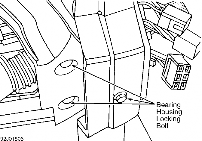
Fig. 12: Loosening Locking Bolts For Bearing Housing (960)
Remove locking ring and spacer ring from steering column. See Fig. 13. Turn ignition switch to "I" position. Push steering column back through bearing housing. Remove ignition key, locking screws for steering lock, and bolt in steering pin.

Fig. 13: Removing Locking Ring & Spacer Ring From Steering Col. (960) Courtesy of Volvo Cars of North America
Lift bearing housing upward while pressing on steering lock with one finger. Remove bearing housing and steering lock under

instrument panel. Disconnect electrical connector from steering lock. Place assembly in a vise. Using center punch, loosen and remove shear bolt. See Fig. 14. Remove ignition switch from bearing housing.
Fig. 14: Removing Shear Bolt (960) Inspection
Check bearing housing bearings, and replace bearings as
necessary. See Fig. 15. Check steering shaft lower bearing race position and ensure surface is not scratched. Race should be installed 1.99" (50.5 mm) from end of shaft. See Fig. 16. Check steering column length. Correct shaft length is 28.59-28.63" (726.2-727.2 mm). See Fig. 17.

Fig. 15: Removing Bearing From Bearing Housing (960) Courtesy of Volvo Cars of North America

Fig. 16: Measuring Bearing Race Distance From End Of Shaft (960)

Fig. 17: Measuring Steering Column Length (960)
Installation
Connect ignition switch connector. Install bearing housing with steering lock, but do not tighten retaining bolts. Install spring and washer on steering column. Install steering column through bulkhead.
Turn ignition key to "I" position. Press steering column into bearing housing. Install spacer ring and locking ring on steering shaft. Ensure locking ring is flush in groove. Tighten bearing housing retaining bolts.
Install lower steering shaft. Torque bolts to 18 ft. lbs. (24 N.m) and install locking pin. Ensure steering and steering lock operate correctly. Remove shear bolts and bolt on steering pin. To complete installation, reverse removal procedure.
Reactivate SRS. See
DISABLING & ACTIVATING AIR BAG SYSTEM . Check SRS warning light to ensure system is functioning properly. If air bag warning light stays on, see the
AIR BAG RESTRAINT SYSTEM article in the ACCESSORIES/SAFETY EQUIPMENT
section.
TORQUE SPECIFICATIONS TABLE
Application Ft. Lbs. (N.m)
Air Bag Torx Screw .................................. ( 1)
Steering Shaft Joint Bolt ........................ 18 (24) Steering Wheel Hub Retaining Bolt ................ 25 (34)
(1) - Tighten to 72 INCH lbs. (8 N.m).
Disclaimer: Volvotips has the exclusive courtesy of Volvo Car Corporation and Volvo Cars Heritage to publish the Volvo Greenbooks (service manual), parts catalogs and other Volvo-material and publications. Commercial use and publishing at other websites of these items is prohibited.