
1994 Volvo 960
1994 ACCESSORIES/SAFETY EQUIPMENT
Cruise Control System
960
MAIN SWITCH
Cruise control main switch is located at end of directional signal lever. Selector switch has 3 positions, OFF, ON and RESUME. SET button is at tip of lever.
BRAKE VALVE
Brake valve is located on the pedal assembly. Two types of valves are used, but their function is identical. Valves are interchangeable.
Older type of valve is adjustable because plunger sleeve is threaded, allowing valve to be adjusted in or out for necessary disengage position. New type of valve adjusts using small plastic catches which hook on to plunger, holding it in place.
When pedal is up (valve actuated), spring is compressed, switch is on and vacuum valve is closed. When pedal is down (valve deactivated), spring pushes plunger back. Electric contact is broken and vacuum valve opens to allow atmospheric pressure into the system.
CONTROL UNIT
of dash.
Control unit is located above pedal assembly, under left side
Control unit receives signals from speed sensor and
switches. Control unit main functions are to decide if system can be controlled based on values and status of input signals, and to regulate system for optimal function.
Control unit also performs diagnostic functions. This enables the unit to communicate with the technician via the under-hood diagnostic hookup.
VACUUM PUMP & REGULATOR
Vacuum pump and regulator are contained in one unit, located on left wheel housing tower. When cruise control system is operating, a 12-volt electric motor pumps vacuum when accelerator is depressed, sucking air out of tube which leads to vacuum servo. Air is pumped out through right coupling. Each coupling is equipped with a check valve to prevent air from entering tube via lower part of pump housing.
Another tube provides constant atmospheric pressure to upper pump housing. Internal regulator releases air to vacuum system when accelerator is released.
VACUUM SERVO
Vacuum servo is located next to throttle linkage. Vacuum servo consists of a housing and bellows. Bellows is pulled toward housing when pressure decreases inside bellows, thereby pulling on wire connecting throttle linkage and bellows.
BRAKE VALVE
Old Type Valve
Play between valve plunger and pedal arm should be .039-.059" (1.0-1.5 mm). See Fig. 1. To adjust, remove vacuum hoses and electrical connector. Adjust valve plunger by turning valve. Check valve function, ensuring valve does not leak.
New Type Valve
Depress pedal until pedal arm does not make contact with valve. Pull out plunger as far as possible and pull pedal up slowly. Plastic catches in valve will hold piston in correct position.
Fig. 1: Adjusting Old Type Brake Valve Courtesy of Volvo Cars of North America
VACUUM SERVO THROTTLE CABLE
Ensure throttle cable is taut at idle. Cable must not affect position of throttle.
NOTE: Diagnostic unit for retrieving codes is located in engine compartment, in front of left strut assembly. Diagnostic unit is equipped with an LED indicator, activation button
and function select cable. See Fig. 2.
All fault codes contain 3 digits (example 3-1-1). Since codes have 3 digits, each code requires 3 series of flashes. A 3-second interval separates series of flashes. Ensure all testing and diagnosis is performed in order.

Fig. 2: Locating Diagnostic Unit Courtesy of Volvo Cars of North America
CONNECTING DIAGNOSTIC SYSTEM
Cruise control diagnostic system does not have a diagnostic hookup, but only a short test lead wire next to control unit. Connect a jumper wire between test lead on control unit and wire on diagnostic unit.
Manufacture an extra jumper wire from Wire (1 323 247-0),
Wire (1 321 258-5) and Splicer (956 956-7). Connect one end of jumper wire to short wire next to control unit. See Fig. 3. Connect other end of wire to diagnostic hookup selector cable.

Fig. 3: Connecting Extra Wire To Control Unit Courtesy of Volvo Cars of North America
TRANSFER RATE TEST MODE
In this test mode, transfer rate (speed of information) between control unit and diagnostic hookup can be changed. This is useful if system is read with a scan tester. See TRANSFER RATE TEST CODES table. This step is not necessary if normal rate is desired, as this rate is loaded with each ignition start.
To enter transfer rate test mode, press diagnostic button
4 times, holding button down about one second each time. When LED lights up, enter selected code. See TRANSFER RATE TEST CODES table. Enter one digit each time LED lights up. Hold button down about one second each time it is pressed. If code is entered correctly, LED will flash code at new rate.
TRANSFER RATE TEST CODES TABLE
Code Function
3-1-1 ........................................ Normal Rate
3-1-2 .................................... ( 1) Double Rate
3-1-3 .......... 10-Times Normal Rate (Display Instrument)
- Recommended for experienced user of diagnostic system only.
COMPONENT TEST MODE
Introduction
This test mode is used to check the components that comprise cruise control system. By activating components one by one, and by giving control unit a response code if control unit has received a signal from component, sensor as well as wiring and connections can be checked. See COMPONENT RESPONSE CODES table.
If no response code is obtained, continue with testing. Repeat SYSTEM COMPONENT CHECK if repairs have been made to ensure system functions properly.
COMPONENT RESPONSE CODES TABLE
Code Activated Component
....................... Selector ON/OFF, Brake Valve
1-2-3 .................................... Selector RESUME
1-3-1 ....................................... Selector SET
1-3-2 .................................. Brakelight Switch
2-2-3 ............................... Neutral Start Switch
3-1-1 .................................... Several Signals
System Component Check
Turn cruise control selector switch to OFF position. Move gear selector to "D". Turn ignition on.
Press diagnostic button twice, each time for one second. If LED starts flashing rapidly (about 6 times a second), go to next step. If LED does not perform as indicated, go to DIAGNOSTIC HOOKUP CHECK.
Depress brake pedal for about one second. If no code is present, go to BRAKELIGHT CHECK. If Code 1-1-3 is present, go to BRAKE VALVE CHECK. If Code 3-1-1 is present, go to SEVERAL SIGNALS CHECK. If Code 1-3-2 is present, go to next step.
Slide cruise control selector switch to ON position. If no code is present, go to BRAKE VALVE CHECK. If Code 3-1-1 is present, go to SEVERAL SIGNALS CHECK. If Code 1-1-3 is present, go to next step.
Depress brake pedal for about one second. If no code is
present, go to BRAKE VALVE CHECK. If Code 3-1-1 is present, go to SEVERAL SIGNALS CHECK. If Code 1-1-3 is present, go to next step.
Press RESUME button on cruise control switch for about one second. If no code is present, go to RESUME BUTTON CHECK. If Code 3-1-
is present, go to SEVERAL SIGNALS CHECK. If Code 1-2-3 is present, go to next step.
Press SET button on cruise control switch for about one second. If no code is present, go to SET BUTTON CHECK. If Code 3-1-1 is present, go to SEVERAL SIGNALS CHECK. If Code 1-3-1 is present, go to next step.
Put transmission shift lever in neutral position. If no code is present, go to NEUTRAL START SWITCH CHECK. If Code 3-1-1 is present, go to SEVERAL SIGNALS CHECK. If Code 2-2-3 is present, go to SERVO SYSTEM TEST.
Brake Valve Check (Response Code 1-1-3)
Turn ignition off. Slide cruise control selector switch to OFF position. Disconnect brake valve electrical connector. Using an ohmmeter, measure resistance between brake valve electrical terminals.
With pedal up, zero ohms should be present. Switch should not close until pedal has traveled more than .30" (8.0 mm). After switch closes, ohmmeter should indicate infinite resistance. If switch operates okay, go to next step. If switch is not okay, replace switch.
Turn ignition on. Slide cruise control selector switch to ON position. Using a voltmeter, measure voltage between control unit terminal No. 3 and ground. With pedal up, battery voltage should be present. With pedal depressed or cruise control selector switch in OFF position, no voltage should be present.
If voltages are not as indicated, check wiring and connectors for open or short circuit. If voltages are as indicated, go to SELECTOR CHECK. If selector checks okay, repeat SYSTEM COMPONENT CHECK. If no response code is generated during SYSTEM COMPONENT CHECK, go to CONTROL UNIT CHECK.
RESUME Button Check (Response Code 1-2-3)
Turn ignition on. Slide cruise control selector switch to ON position. Using a voltmeter, measure voltage between control unit terminal No. 4 and ground. See Fig. 4. Slide cruise control switch to RESUME position. Voltmeter should indicate battery voltage. With switch in other positions, voltmeter should indicate zero voltage.
If voltage is not as indicated, check wiring and connectors for open or short circuit. If voltage is as indicated, go to SELECTOR CHECK. If selector checks okay, repeat SYSTEM COMPONENT CHECK. If no response code is generated during SYSTEM COMPONENT CHECK, go to CONTROL UNIT CHECK.

Fig. 4: Identifying Control Unit Terminals Courtesy of Volvo Cars of North America
SET Button Check (Response Code 1-3-1)
Turn ignition on. Slide cruise control selector switch to
ON position. Using a voltmeter, measure voltage between control unit terminal No. 6 and ground. See Fig. 4. Slide cruise control switch to RESUME position. Voltmeter should indicate battery voltage. With switch in other positions, voltmeter should indicate zero voltage.
If voltage is not as indicated, check wiring and connectors for open or short circuit. If voltage is as indicated, go to SELECTOR CHECK. If selector checks okay, repeat SYSTEM COMPONENT CHECK. If no response code is generated during SYSTEM COMPONENT CHECK, go to CONTROL UNIT CHECK.
Brakelight Check (Response Code 1-3-2)
Ensure brakelights illuminate when pedal is depressed. If not, check bulb, fuse and wiring as necessary.
Using an ohmmeter, check continuity between control unit terminal No. 7 and ground. See Fig. 4. Ohmmeter should indicate approximately zero ohms since terminal No. 7 and brakelight bulbs are connected to ground through brakelight bulbs.
If ohmmeter does not indicate approximately zero ohms, check wiring and connectors for an open or short circuit. If ohms are to specification, adjust brakelight switch so brakelights illuminate when pedal is depressed .31-.51" (8-14 mm). If brakelight switch is okay, repeat SYSTEM COMPONENT CHECK. If no response code is generated during SYSTEM COMPONENT CHECK, go to CONTROL UNIT CHECK.
Neutral Start Switch Check (Response Code 2-2-3)
Turn ignition off. Disconnect control unit connector. Using an ohmmeter, measure resistance between control unit terminal No. 2 and ground. See Fig. 4. Ensure resistances are to specification as transmission shift lever is moved. See NEUTRAL START SWITCH RESISTANCE SPECIFICATIONS table.
If resistances are not to specification, check switch, wiring and connections for an open or short circuit. If resistances are to specification, repeat SYSTEM COMPONENT CHECK. If no response code is generated during SYSTEM COMPONENT CHECK, go to CONTROL UNIT CHECK.
NEUTRAL START SWITCH RESISTANCE SPECIFICATIONS TABLE
Shift Lever Position Ohms
P ............................................... ( 1) Zero
R ............................................... Infinite
N ............................................... ( 1) Zero
D ............................................... Infinite
Other Positions ................................. Infinite
- This specification is approximate.
Several Signals Check (Response Code 3-1-1)
Code 3-1-1 is obtained when control unit receives several signals simultaneously. This situation is usually caused by a short circuit in one or more circuits.
Most likely areas of fault when a Code 3-1-1 is obtained include signal from brakelight circuit (control unit terminals No. 7 and 10), neutral start switch (control unit terminal No. 2) and selector (control unit terminals No. 11, 6, 4 and 3). See Fig. 4.
Selector Check
Turn ignition off. Disconnect control unit connector. Using an ohmmeter, measure resistance between control unit terminals No. 3 and 11, or between selector connector terminals No. 1 and 2. See CHECKING ON & OFF FUNCTION table.
To check resume function of switch, use an ohmmeter and measure resistance between control unit terminals No. 4 and 11 or between selector connector terminals No. 3 and 2. See CHECKING RESUME FUNCTION table.
To check set function of switch, use an ohmmeter to measure resistance between control unit terminals No. 6 and 11 or between selector connector terminals No. 4 and 2. See CHECKING SET FUNCTION table.
To check other switch functions, measure resistance between control unit terminals No. 3 and 4 or selector connector terminals No. 1 and 3. See CHECKING OTHER FUNCTIONS table (Step 1).
Using an ohmmeter, measure resistance between control unit terminals No. 3 and 6 or between selector terminals No. 1 and 4. See CHECKING OTHER FUNCTIONS table (Step 2).
Using an ohmmeter, measure resistance between control unit terminals No. 4 and 6 or between selector terminals No. 3 and 4. See CHECKING OTHER FUNCTIONS table (Step 3).
If all measurements are okay, selector switch and wiring are okay. If any resistance measurements are not to specification, check wiring and connections for an open or short circuit.
CHECKING ON & OFF FUNCTION TABLE
Switch Position Ohms
OFF
SET Button Out ................................ Infinite
SET Button In ................................. Infinite ON
SET Button Out ................................ ( 1) Zero
SET Button In ................................. ( 1) Zero RESUME
SET Button Out ................................ ( 1) Zero
SET Button In ................................. ( 1) Zero
Brake Pedal Depressed
SET Button Out ................................ Infinite
SET Button In ................................. Infinite
(1) - This specification is approximate.
CHECKING RESUME FUNCTION TABLE
Switch Position Ohms
OFF
SET Button Out ................................ Infinite
SET Button In ................................. Infinite ON
SET Button Out ................................ Infinite
SET Button In ................................. ( 1) Zero RESUME
SET Button Out ................................ Infinite
SET Button In ................................. ( 1) Zero
(1) - This specification is approximate.
CHECKING SET FUNCTION TABLE
Switch Position Ohms
OFF
SET Button Out ................................ Infinite
SET Button In ................................. Infinite ON
SET Button Out ................................ Infinite
SET Button In ................................. ( 1) Zero RESUME
SET Button Out ................................ Infinite
SET Button In ................................. ( 1) Zero
(1) - This specification is approximate.
CHECKING OTHER FUNCTIONS TABLE
Switch Position Ohms
Step 1 OFF
SET Button Out ............................... Infinite
SET Button In ................................ Infinite ON
SET Button Out ............................... Infinite
SET Button In ................................ Infinite RESUME
SET Button Out ............................... ( 1) Zero
SET Button In ................................ ( 1) Zero
Step 2 OFF
SET Button Out ............................... Infinite
SET Button In ................................ ( 1) Zero ON
SET Button Out ............................... Infinite
SET Button In ................................ ( 1) Zero RESUME
SET Button Out ............................... ( 1) Zero
SET Button In ................................ ( 1) Zero
Step 3 OFF
SET Button Out ............................... Infinite
SET Button In ................................ Infinite ON
SET Button Out ............................... Infinite
SET Button In ................................ Infinite RESUME
SET Button Out ............................... Infinite
SET Button In ................................ ( 1) Zero
- This specification is approximate.
Diagnostic Hookup Check
Turn ignition on. Ensure auxiliary cable between diagnostic hookup and control unit is okay. Check control unit. See CONTROL UNIT CHECK. Disconnect diagnostic hookup connector. Using a voltmeter, ensure battery voltage is present between terminal No. 4 and ground. See Fig. 5.
Turn ignition off. Use an ohmmeter to measure resistance between connector terminal No. 8 and ground. See Fig. 6. If ohmmeter indicates approximately zero ohms, go to next step. If not, check wiring and connectors for an open or short circuit.
Use an ohmmeter and measure resistance between selector cable and pin under diagnostic button. See Fig. 7. Infinite resistance should be present with diagnostic button up. With diagnostic button
down, zero ohms should be present.
Using a diode tester, take a measurement with Red probe of diode tester on pin under LED, and Black probe on selector cable. See Fig. 8. If diode is inoperable, repair as necessary. If diode is okay, repeat SYSTEM COMPONENT CHECK. If no response code is generated during SYSTEM COMPONENT CHECK, go to CONTROL UNIT CHECK.
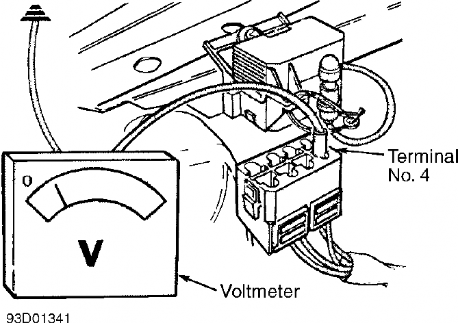
Fig. 5: Checking Voltage Between Terminal No. 4 & Ground Courtesy of Volvo Cars of North America

Fig. 6: Checking Resistance Between Terminal No. 8 & Ground Courtesy of Volvo Cars of North America

Fig. 7: Checking Resistance Between Selector Cable & Pin Courtesy of Volvo Cars of North America

Fig. 8: Checking Diode Between Selector Cable & Pin Courtesy of Volvo Cars of North America
Control Unit Check
Turn ignition on. Slide selector switch to ON position.
Leave control unit connector connected. Using a voltmeter, measure voltage between control unit connector terminal No. 3 and ground point located at left or right "A" pillar. See Fig. 4. Battery voltage should be present.
Using a voltmeter, measure voltage between control unit connector terminals No. 10 and 11. Battery voltage should be present.
Turn ignition off. Disconnect control unit connector. Slide cruise control selector switch to ON position. Using an ohmmeter, measure resistance between control unit connector terminal No. 11 and fuse terminal No. 2 (located in fuse panel). Fuse panel is located on left side of instrument panel. Ohmmeter should indicate about zero ohms.
Using an ohmmeter, measure resistance between terminal No.
at fuse and control unit connector terminal No. 3. Ohmmeter should indicate about zero ohms.
Using an ohmmeter, measure resistance between control unit connector terminal No. 10 and ground at steering column. Ohmmeter should indicate approximately zero ohms. If all tests check okay, install a new control unit and retest. If all tests do not check okay, check wiring and connectors for open or short circuits.
SERVO SYSTEM TEST
NOTE: Test is performed by operating vacuum pump and regulator with Jumper Wire Set (9 813 181) attached to control unit connector. If jumper wires are incorrectly connected, components may be damaged. Use special care when performing this test.
Attaching Jumper Wire Set (9 813 181) To Control Unit Conn.
Disconnect control unit connector. Connect Red jumper wire between control unit connector terminals No. 1 and 11 (voltage feed to vacuum pump and regulator.) Connect Black wire to control unit connector terminal No. 10 (ground). See Fig. 9.
Connect Orange wire to control unit connector terminal No.
12 (regulator ground connection). Connect Yellow/Green wire to control unit terminal No. 9 (vacuum pump ground connection).

Fig. 9: Attaching Jumper Wire Set (9 813 181) To Control Unit Courtesy of Volvo Cars of North America
Voltage Feed Check
Disconnect control unit connector. Attach Jumper Wire Set
(9 813 181) to control unit connector. Turn ignition on. Using a voltmeter, measure voltage between Black wire and Red wire. If battery voltage is present, go to next step. If battery voltage is not present, check fuses and wiring.
Connect Orange wire to Black wire. If regulator clicks, go to next step. If regulator does not click, check wiring to regulator.
Connect Yellow/Green wire to Black wire. If vacuum pump starts and vacuum servo pulls throttle to full-open position, go to next step. If not, check wiring and vacuum hoses to vacuum pump and vacuum servo.
Disconnect Yellow/Green wire to stop vacuum pump. Depress brake pedal. If brake valve aerates system and vacuum servo releases, go to next step. If not, replace brake valve.
Connect Yellow/Green wire to Black wire, and operate vacuum pump. Disconnect Yellow/Green and Black wires after 30 seconds. If vacuum servo still holds throttle wire open after 30 seconds, no leaks are present in vacuum system.
Disconnect Orange wire. Regulator should click and vacuum servo should release throttle. If all components operate to specification, vacuum system is okay. If all components do not operate to specification, check vacuum hoses and connections in vacuum system and repair as necessary. Road test vehicle. If a fault is present while driving, system will set a code. Go to SELF-DIAGNOSTICS. Note that all fault codes are erased once engine is turned off.
TEST FUNCTION NO. 1
Codes stored in Test Function No. 1 should be read after a road test because cruise control self diagnostics does not store codes, but rather erases them when ignition is turned off. Road test must exceed 22 MPH, otherwise Code 1-2-2 will always be given to indicate speed has not reached minimum speed.
NOTE: If engine is turned off after road test, Code 1-2-2 will be stored. Road test must be repeated.
Beginning Test Function No. 1
Press diagnostic button once for about one second. Read and note code. Check if more than one code is stored by pressing diagnostic button once more for about one second. Read and note all codes until first code is repeated. See SELF-DIAGNOSTIC CODES table.
SELF-DIAGNOSTIC CODES TABLE
Code Fault
1-1-1 ........................................... No Fault
1-1-2 .............................. Abnormal Speed Signal
...................... Speed Below Minimum/No Signal 2-1-1 ............. Voltage Speed/Control Unit Malfunction 2-1-2 ....... Vacuum Pump or Regulator Circuit Malfunction
Code 1-1-2 & Code 1-2-2
Code 1-1-2 is stored if a safety feature has been tripped, or an abnormal speed signal. The code is stored only if control unit has had a normal signal at some time during road test and not for stationary interruptions. Code 1-2-2 is stored when ignition is turned on. It remains until vehicle speed has been greater than 22 MPH for at least 15 seconds. If code remains after a road test at speeds greater
than 22 MPH, control unit is not getting a speed signal.
Turn ignition on. Slide cruise control selector switch to ON position. Leave control unit connector connected and measure voltage between terminals No. 10 and 11. See Fig. 4. Voltmeter should indicate battery voltage.
Turn ignition off. Slide cruise control selector switch to ON position. Disconnect control unit connector. Using an ohmmeter, measure resistance between control unit connector terminal No. 11 and fuse terminal No. 2 (located in fuse panel). Fuse panel is located on left side of instrument panel. Ohmmeter should indicate zero ohms.
Leave control unit connector disconnected. Using an ohmmeter, measure resistance between control unit connector terminal No. 10 and steering column ground. Ohmmeter should indicate about zero ohms. Ensure speedometer and control unit are grounded in same location.
Turn ignition on. Reconnect control unit connector. Raise and support vehicle so rear wheels are off the ground. Using a voltmeter, measure voltage between terminal No. 13 and ground. Slowly rotate one rear wheel. If voltmeter oscillates between 1.5-12 volts, system is operating correctly. Check circuit for possible static from other systems.
If voltage does not oscillate, check wiring for an open or short circuit. Check wire between control unit and speedometer first. If wire is okay, check wiring between speedometer and rear axle sensor.
Code 2-1-1 & Code 2-1-2
Code 2-1-1 is stored if voltage feed, ground or control unit is bad. If control unit does not receive correct voltage, or if ground is bad, cruise control will not function. For cruise control system to function, voltage must be a minimum of 10.5 volts.
Code 2-1-2 is stored if a short circuit exists to ground or battery voltage exists in circuit to vacuum pump and regulator. Fault may also be in control unit. If a Code 2-1-2 fault code is present, test servo system before performing self diagnosis. See SERVO SYSTEM TEST under DIAGNOSIS & TESTING.
Turn ignition on. Slide cruise control switch to ON position. Leave control unit connector connected. Using a voltmeter, measure voltage between control unit terminal No. 3 and ground. See Fig. 4. Battery voltage should be present. Using voltmeter, measure voltage between terminal No. 10 and 11. If battery voltage is present, go to next step. If battery voltage is not present, check wiring and grounds as necessary.
Turn ignition off. Slide cruise control selector switch to ON position. Disconnect control unit connector. Using an ohmmeter, measure resistance between terminal No. 2 on fuse panel and control unit connector terminal No. 11. Fuse panel is located on left side of instrument panel. Ohmmeter should indicate zero ohms.
Using an ohmmeter, measure resistance between terminal No.
2 on fuse panel and control unit connector terminal No. 3. Ohmmeter should indicate zero ohms. Use an ohmmeter and measure resistance between control unit terminal No. 10 and steering column (ground). Ohmmeter should indicate zero ohms. If all resistances are okay, test system with a new control unit. If all resistances are not okay, check wiring and connections as necessary.
TEST FUNCTION NO. 2
Codes stored in Test Function No. 2 show most recent reason for cruise control disengagement. This test function can be used when cruise control disengages without driver input. Code remains in memory until ignition is turned off, or until cruise control is disconnected. These codes are not necessarily fault codes, since a code is also
stored after normal disengagement. See DISENGAGEMENT CODES table. DISENGAGEMENT CODES TABLE
Code Disengagement Cause
1-1-4 ............................... Safety Disengagement 1-4-1 ......... Neutral Start Switch Circuit Disengagement 4-1-1 ....................... Brake Selector Disengagement
................... Brakelight Circuit Disengagement 2-1-4 ........... Voltage Feed Not Connected/Disengagement
Beginning Test Function No. 2
Press diagnostic button 5 times, holding button down approximately one second each time. When LED lights up, enter 1-1-1 (one press each time LED lights). Hold button down about one second each time. Read response code.
Code 1-1-4 (Safety Disengagement)
Code 1-1-4 is set in event of a safety disengagement. Safety disengagement does not necessarily mean something is wrong with system. Cruise control system disengages automatically during abnormal conditions such as wheel spin, climbing a steep hill, etc. If this code is set without a normal safety disengagement, check speed signal circuit. See CODE 1-1-2 & CODE 1-2-2 under TEST FUNCTION NO. 1 under SELF DIAGNOSTICS.
Code 1-4-1 (Neutral Start Switch Circuit Disengagement)
Code 1-4-1 is set if cruise control is disengaged when transmission shift lever is set in "P" or "N" position. If this code is set without shift lever in one of these positions, control unit terminal No. 2 was grounded at moment of disengagement. See NEUTRAL START SWITCH CHECK (RESPONSE CODE 2-2-3) under COMPONENT TEST MODE under DIAGNOSIS & TESTING.
Code 4-1-1 (Brake Selector Disengagement)
Code 4-1-1 is set if cruise control is disengaged by sliding selector to OFF position or depressing brake pedal. Otherwise, control unit terminal No. 3 did not have battery voltage at moment of disengagement. This may be caused by play in selector, loose wires and connectors or incorrectly adjusted brake valve. See BRAKE VALVE CHECK (RESPONSE CODE 1-1-3) under COMPONENT TEST MODE under DIAGNOSIS & TESTING.
Code 1-2-4 (Brakelight Circuit Disengagement)
Code 1-2-4 is set if cruise control is disengaged by depressing brake pedal and closing brakelight switch. Otherwise, control unit terminal No. 7 was not connected to ground through brakelight bulbs at moment of disengagement. Check for loose wires or connectors and an incorrectly adjusted brakelight switch. See BRAKELIGHT CHECK (RESPONSE CODE 1-3-2) under COMPONENT TEST MODE under DIAGNOSIS & TESTING.
Code 2-1-4 (Voltage Feed Not Connected/Disengagement)
Code 2-1-4 is set when ignition is turned on and remains stored until cruise control is engaged using SET one time and disengaged once. Reason for disengagement is then stored instead of Code 2-1-4.
If Code 2-1-4 is set after disengagement during a test drive, without engine having been turned off, voltage to control unit has fallen below minimum level. See CONTROL UNIT CHECK under COMPONENT TEST MODE under DIAGNOSIS & TESTING.
BRAKE VALVE
Removal & Installation
Brake valve is located at brake pedal. Remove clip, vacuum hoses and connectors from valve. Use care not to damage rubber seals. To install, reverse removal procedure. Adjust valve. See BRAKE VALVE under ADJUSTMENTS.
CRUISE CONTROL SWITCH
Removal & Installation
Turn ignition off. Remove upper and lower steering column covers. Pull off selector connector and remove 2 screws holding selector in place. To install, reverse removal procedure.
BRAKELIGHT SWITCH
Removal & Installation
Remove brakelight fuse. Remove brakelight switch connector. Remove brakelight switch. To install, reverse removal procedure.
VACUUM SERVO
Removal & Installation
Remove vacuum hose and throttle cable at vacuum servo. Use care not to damage rubber seals. Unscrew vacuum servo from retaining bracket. To install, reverse removal procedure. Ensure throttle cable is taut at idle. Cable must not affect position of throttle.
VACUUM PUMP & REGULATOR
Removal & Installation
Remove vacuum hoses and vacuum pump connector. Using a Torx screwdriver, unscrew vacuum pump from left wheel housing. To install, reverse removal procedure.

Fig. 10: Cruise Control System Wiring Diagram (960)
Disclaimer: Volvotips has the exclusive courtesy of Volvo Car Corporation and Volvo Cars Heritage to publish the Volvo Greenbooks (service manual), parts catalogs and other Volvo-material and publications. Commercial use and publishing at other websites of these items is prohibited.