1994 Volvo 960
1994 BRAKES
Volvo Brake System - Anti-Lock
960
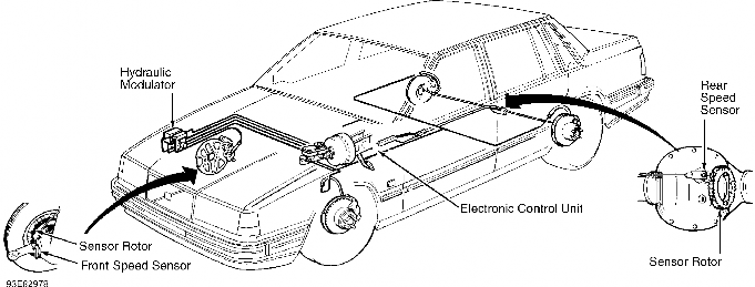
Anti-Lock Brake System (ABS) consists of speed sensors (on both front rotors and in rear axle), an Electronic Control Unit (ECU) (under left side of instrument panel), and a hydraulic modulator (in engine compartment). See Fig. 1.
The hydraulic modulator consists of front and rear pressure control solenoids and relays, a return motor pump and relay, and an ECU connector. Modulator pressure control solenoids are mounted inside hydraulic modulator and are not individually serviceable. Replace modulator assembly if solenoids are defective.
An ABS warning light in instrument panel will remain illuminated if an ABS failure occurs. If an ABS malfunction occurs, conventional braking system takes over. Vehicle may be safely driven when ABS warning light is on.
NOTE: For more information on brakes, see BRAKE SYSTEM article in the BRAKES section.
Fig. 1: Locating ABS Components Courtesy of Volvo Cars of North America
Hydraulic system consists of master cylinder, delivery lines, hydraulic modulator, electric solenoid valves, return delivery pump and brake calipers. Solenoid valves are contained within hydraulic modulator. Individual solenoid valves are used for pressure control to left and right front calipers, while rear brake line pressure is controlled by a common, regulated rear solenoid valve.
Hydraulic modulator controls hydraulic pressure to each front brake caliper or both rear calipers independent of pressure produced by brake master cylinder. However, pressure cannot exceed master cylinder pressure.
If wheel lock-up is sensed by speed sensors, ECU sends signal to hydraulic modulator. Hydraulic modulator operates electric return delivery pump to reduce hydraulic pressure at brake caliper(s). This is repeated until lock-up is eliminated.
ABS system has 2 relays (solenoid valve relay and pump motor relay), mounted on top of hydraulic modulator. Battery voltage is supplied to relays through fuse panel. ECU supplies a ground for relays when vehicle is in operation. This ECU-controlled ground supplies voltage signal from solenoid valve relay to front-control solenoid and to rear-control solenoid. Based upon speed sensor signals, ECU controls solenoid operation by supplying ground to energize individual solenoids.
Return delivery pump motor relay closes when ground is provided through control unit. Pressure relieved by solenoid valve operation is returned to master cylinder by return delivery pump motor operation.
WARNING: See ANTI-LOCK BRAKE SAFETY PRECAUTIONS article in GENERAL
INFORMATION section.
NOTE: Use only DOT 4 grade brake fluid.
Fill brake fluid reservoir to MAX level. Connect hoses to both bleed valves on left rear wheel. Submerge hoses in bottle containing brake fluid. Both hoses must be below brake fluid surface.
Open bleed valves. Have an assistant slowly pump brake pedal 5 times, holding pedal down on last depression stroke. No air bubbles should be visible after last stroke. Close all bleeders.
Check brake fluid level after each open-and-close cycle of bleeders. Bleed remaining wheels in the following order: right rear, left front and right front.
NOTE: For adjustment information, see BRAKE SYSTEM article in the BRAKES section.
ABS WARNING LIGHT
ABS warning light on instrument cluster should go out after starting engine, indicating system is okay. Individual components can be tested with appropriate test equipment. See DIAGNOSIS & TESTING.
PRE-DIAGNOSIS INSPECTION
Perform a comprehensive visual inspection of system components before testing ABS system to isolate simple failures.
ABS REPAIR PRECAUTIONS
Observe the following precautions when performing repairs:
Disconnect battery or electronic components with ignition
switch in ON position.
Disconnect ECU connector when arc welding on vehicle.
NEVER subject ECU to temperatures greater than 180 F (82 C).
DO NOT Disconnect battery before charging with fast charger.
DO NOT use fast charger to start engine.
NOTE: Test all ABS components and wiring before replacing ECU.
To prepare for testing, turn ignition switch to OFF position. Remove cover from hydraulic modulator. Remove ECU connector by depressing lock spring and swinging out connector. Leave ECU connector unplugged, unless stated otherwise in testing procedure. Consult wiring diagram while performing tests. See WIRING DIAGRAMS in this article. Check ECU connector terminals only through slots in side of connector. DO NOT use more force than necessary. Connector terminal numbers are molded into side of connector. To reduce diagnostic time, test components in the following order.
FUSES
Check 10-amp transient surge protector fuse. Transient surge protector is clipped to ECU. See Fig. 1.
ABS CIRCUIT TESTS
Ground Circuits
Turn ignition off. Disconnect ECU connector. See Figs. 1 and 2. Using DVOM, check resistance between ECU connector terminals No. 10, 20, 32 and 34 and ground. Resistance should be zero in all cases.
CAUTION: Never probe front of connectors. Check connectors only through slots in side of connector. DO NOT use more force than necessary. See Fig. 2.
If resistance is not correct, check wiring harness between ECU and ground connections. Terminals No. 10, 20, and 34 are grounded at left "A" pillar. If fault is found at terminal No. 32, retest with new solenoid valve relay. See Fig. 5.

Fig. 2: Accessing ECU Connector Test Slots Courtesy of Volvo Cars of North America
Transient Surge Protector
Disconnect ECU connector. See Figs. 1 and 2. Turn ignition
on. Connect DVOM between terminal No. 1 on ECU connector and ground. DVOM should read battery voltage. If battery voltage is not present, measure voltage on transient surge protector connector. Transient surge protector is clipped to ECU.
Terminals No. 1, 2, and 4 should have battery voltage. Check for continuity between terminal No. 3 and ground. If only terminals No. 1 and 4 have voltage when terminal No. 3 is grounded, replace transient surge protector.
ECU Power Circuits
Turn ignition on. Disconnect ECU connector. See Figs. 1 and 2. Connect negative lead of DVOM to ground. Check for voltage at terminal No. 25 (while depressing brake pedal), and at terminals No. 27, 28 and 29 of ECU connector. All terminals should have battery voltage except for terminal No. 29, which should have .5-1.0 volt.
If no voltage is present at the following terminals, perform appropriate repair:
No. 25 - Check brakelight switch. Replace if defective.
No. 27 - Replace defective solenoid valve relay.
No. 28 - Replace defective pump motor relay.
No. 29 - If voltage reading at terminal No. 27 is correct, voltage at terminal No. 29 should be .5-1.0 volt. If voltage at terminal No. 29 is not correct, replace solenoid relay.
Hydraulic Modulator Power Circuits
Turn ignition off. Disconnect hydraulic modulator connector. Turn ignition on.
Connect DVOM negative lead to ground and positive lead to hydraulic modulator connector terminals No. 6, 7, 10 and 12. DVOM should indicate battery voltage. If battery voltage is not present, perform the following repairs:
No. 6 - Check wire harness and fuses.
No. 7 - Attach connector to hydraulic modulator. ABS warning light should illuminate. If light does not illuminate, replace bulb.
No. 10 - Check transient surge protector fuse. If fuse is okay, replace transient surge protector.
No. 12 - Check wire harness and 80-amp fuse on top of right front wheelwell.
Turn ignition switch off. Attach connector to modulator.
SENSORS
Front Speed Sensors
Disconnect ECU connector. See Figs. 1 and 2. Using DVOM, check resistance between ECU connector terminals No. 4 and 6 (left sensor). Check resistance between ECU connector terminals No. 11 and
21 (right sensor). Resistance should vary from 900-2200 ohms as wheel is rotated.
If resistance is not within specification, check resistance at sensor connectors on suspension tower in engine compartment. If resistance is within specification, repair wiring harness to ECU. If resistance is not within specification, replace sensor. See Fig. 3.
Check pulse wheels for damage. Maximum radial run-out is . 006" (.15 mm).

Fig. 3: Locating ABS Front Speed Sensor Courtesy of Volvo Cars of North America
Rear (Axle) Speed Sensor
Disconnect ECU connector. See Figs. 1 and 2. Connect DVOM between ECU connector terminals No. 7 and 9. Resistance should vary from 600-1600 ohms as rear wheels are rotated.
If resistance is not within specification, check sensor resistance at sensor connector at fuel filler pipe in trunk. If resistance is within specification, repair wiring harness to ECU. If resistance is not within specification, replace sensor. See Fig. 4.
On vehicles without multi-link axle, if gap between sensor and pulse wheel is greater than .007" (.2 mm) or has damaged teeth, sensor gives incorrect signals and must be replaced.

Fig. 4: Locating ABS Rear Speed Sensor Courtesy of Volvo Cars of North America
SOLENOIDS
Hydraulic Modulator
Turn ignition off. Disconnect ECU connector. See Figs. 1 and 2. Connect DVOM between ECU connector terminals No. 32 and 2 to check left front control solenoid. Connect DVOM between ECU connector terminals No. 18 (rear control solenoid) and No. 35 (right front control solenoid). Resistance should be .7-1.7 ohms.
If resistance is not within specification, unplug hydraulic modulator connector. Test resistance between hydraulic modulator terminal No. 4 (ground) and hydraulic modulator terminals No. 1, 3, and 5. If readings are within specification, repair ECU wiring harness to modulator. If readings are not within specification, replace hydraulic modulator. See HYDRAULIC MODULATOR under REMOVAL & INSTALLATION.
RELAYS
Return Pump Motor Relay
Disconnect ECU connector. See Figs. 1 and 2. Turn ignition on. Connect jumper wire between ECU connector terminal No. 28 and ground.
NOTE: Relay should not remain grounded for more than 2 seconds, or damage to relay may occur.
Simultaneously measure voltage across connector terminal No. 14 and ground. Battery voltage should be present. If hydraulic modulator does not function, check wiring from ECU connector to modulator. If wiring is not faulty, replace and retest relay. See Fig. 5.
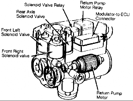
Fig. 5: Identifying Hydraulic Modulator Assembly Courtesy of Volvo Cars of North America
Solenoid Valve Relay
Disconnect ECU connector. See Figs. 1 and 2. Turn ignition
on. Connect DVOM between ground and terminal No. 32 of ECU connector. Connect jumper wire between ECU connector terminal No. 27 and ground.
Solenoid valve relay should switch on and DVOM should read battery voltage. If solenoid valve is inoperative and DVOM does not read battery voltage, check wiring harness from ECU connector and hydraulic modulator. If wiring is not faulty, replace relay and retest. See Fig. 5.
ELECTRONIC CONTROL UNIT
If all other ABS components test okay, replace ECU with known good unit and check ABS operation.
ELECTRONIC CONTROL UNIT
Removal & Installation
Disconnect negative battery cable. Remove lower dash panel and knee bolster from under steering column. ECU is located behind upper left instrument panel, strapped into vertically-mounted bracket. See Fig. 1.
Release strap buckle and pull ECU down and out. Unplug connector without bending terminal pins. See Fig. 2. To install, reverse removal procedure.
HYDRAULIC MODULATOR
Removal & Installation
Disconnect negative battery cable. Remove cover from hydraulic modulator, located on right inner fender panel. See Fig. 1. Remove solenoid valve and return pump relays from modulator. See
Fig. 5. Unplug modulator harness connector.
Disconnect ground strap from connector end of modulator. Carefully clean and remove brake line connections, noting position of lines on modulator. Remove nuts from rubber modulator mounts.
Place rags under hydraulic modulator to collect brake fluid. Disconnect brake lines. Remove hydraulic modulator. To install, reverse removal procedure. See BLEEDING BRAKE SYSTEM.
SPEED SENSORS
Removal & Installation (Front Speed Sensor)
Locate sensor wires at sensor. See Fig. 3. Follow sensor wire to connector on spring tower. Disconnect sensor wires from connector. Pull wires through wheel arch and release from clamps.
Unbolt sensor from inboard side of spindle arm. Remove sensor. Before installing, coat speed sensor with small amount of Grease (1 161 037-5). To complete installation, reverse removal procedure.
Removal (Rear Speed Sensor Straight Axle)
Follow sensor wires from sensor to connector. See Fig. 4. Cut shrink tubing from connector (if applicable). Unplug connector. Pull sensor wiring from below vehicle. Unbolt sensor from differential cover. Remove sensor.
Installation
To install, reverse removal procedure. Tighten sensor bolt to 8-12 ft. lbs. (11-16 N.m).
Removal (Rear Speed Sensor Multi-Link Axle)
Remove spare tire. Fold carpet back to expose fuel filler pipe. Follow sensor wires from sensor. Cut shrink tubing from connector (if applicable). Disconnect connector. Press out sensor cable and rubber grommet.
Raise and support rear axle. Remove 4 bolts holding axle to body. Slightly lower rear axle. Disconnect right parking brake cable to allow access to sensor. Clean area around sensor. Remove sensor.
Installation
To install, reverse removal procedure. Tighten sensor screws to 8-12 ft. lbs. (11-16 N.m). Tighten rear axle-to-body bolts to 52 ft. lbs. (70 N.m), and then tighten bolts an additional 70 degrees.
SENSOR ROTOR
Removal
Raise and support vehicle. Remove wheel assembly. Remove 2 caliper retaining bolts. Remove caliper and hang aside. Remove brake rotor. Place thumb on bearing so it does not fall out, and pull off sensor rotor.
Installation
Press new sensor rotor onto hub. Slide sensor rotor onto spindle. Install outer wheel bearing and nut. Tighten nut to 42 ft. lbs. (57 N.m) while turning rotor. Loosen nut 1/2 turn. Ensure outer bearing inner race is not stuck. Tighten nut finger tight, then tighten nut to closest hole and insert cotter pin.
Install brake rotor. Install brake caliper using new attaching bolts. Tighten caliper bolts to specification. See TORQUE SPECIFICATIONS. To complete installation, reverse removal procedure.
TORQUE SPECIFICATIONS TABLE
Application Ft. Lbs. (N.m)
Front Caliper Mounting Bolts .................... 74 (100)
Front Wheel Bearing Nut .......................... 42 (57)
Master Cylinder Mounting Bolts ................... 22 (30) Rear Axle-To-Body Bolts .......................... 52 (70)
Sensor Bolt/Screw ........................... 8-12 (11-16)
Wheel Lug Nuts ................................... 63 (86)

Fig. 6: Anti-Lock Brake System Wiring Diagram (960)
Disclaimer: Volvotips has the exclusive courtesy of Volvo Car Corporation and Volvo Cars Heritage to publish the Volvo Greenbooks (service manual), parts catalogs and other Volvo-material and publications. Commercial use and publishing at other websites of these items is prohibited.